✳Wood-Frame Construction Basics: The Visual Guide for New Builders in the U.S.✳EPA 608 Certification: The Visual Study Guide for HVAC/R Technicians✳Home Repair Basics: The Visual Guide for New Homeowners✳Practical Electronics from Scratch: The Visual Guide✳Automotive Oscilloscope Diagnostics: The Visual Guide for Technicians✳Automotive Electrical Systems: The Practical Visual Guide✳PLC Programming from Zero: The Visual Guide to Ladder Logic✳Industrial Pneumatics and Hydraulics: The Visual Guide✳High-Protein Meal Prep: The Visual Recipe Guide✳Hands-On Learning Activity Book for Kids Ages 4-8
Need help? ↗

4 real pages from the book · tap one to enlarge

BUSINESS & ENTREPRENEURSHIP · EDITION UNITED STATES · English · 70 PAGES

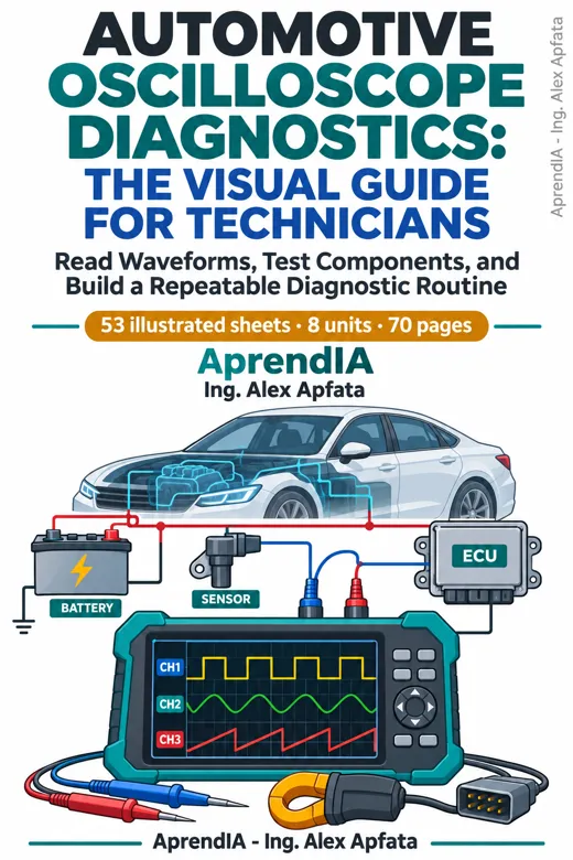
Automotive Oscilloscope Diagnostics: The Visual Guide for Technicians

Read Waveforms, Test Components, and Build a Repeatable Diagnostic Routine

$27.00USD · PDF

Over 5,000 guides delivered every month

INSIDE THIS GUIDE

What you will learn.

See the pages ↑
  1. 01

    Set voltage/div, time/div, and trigger controls, then choose a safe connection for the circuit you are testing.

  2. 02

    Read sensor, ignition, injector, and CAN waveforms with labeled diagrams and practical comparison checklists.

  3. 03

    Use relative compression, charging ripple, and known-good captures to plan your next test and verify your repair.

TABLE OF CONTENTS

Everything inside, unit by unit.

8 units · 53 topics

  1. Unit 1: Understand What Your Scope Shows

    1. See What a Multimeter Can Miss
    2. Read the Voltage and Time Axes
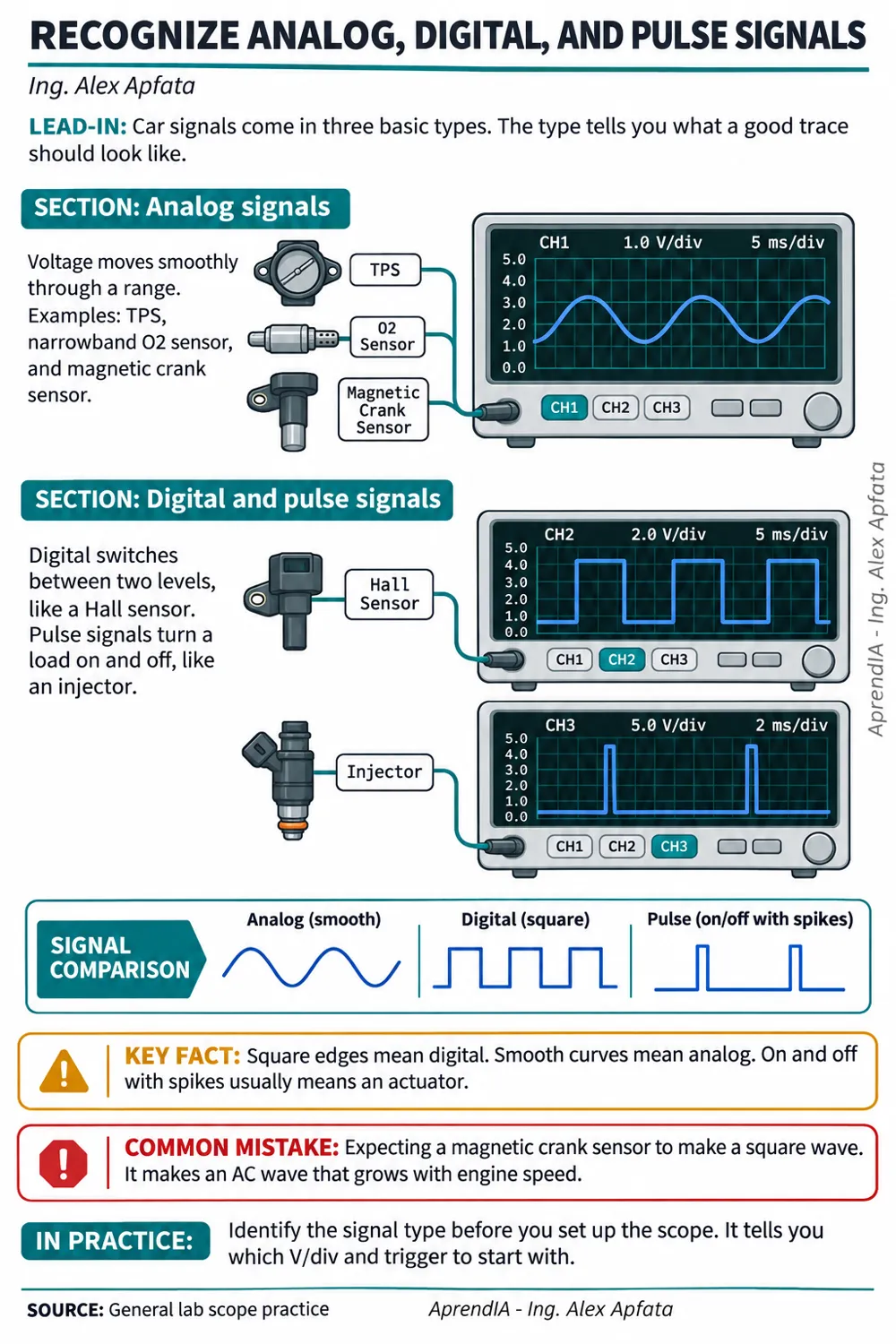
    3. Recognize Analog, Digital, and Pulse Signals
    4. Measure Amplitude, Period, and Frequency
    5. Read Pulse Width and Duty Cycle
    6. Connect Waveform Features to Circuit Operation
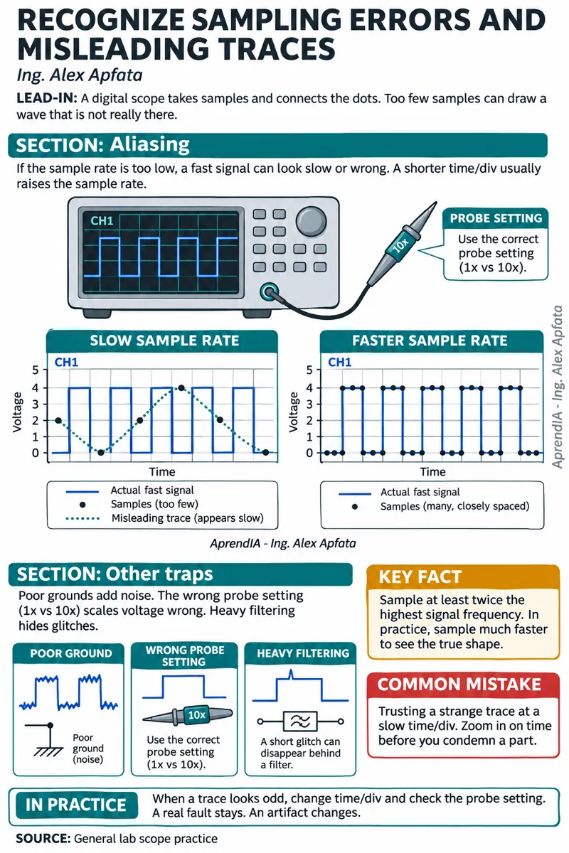
    7. Recognize Sampling Errors and Misleading Traces
  2. Unit 2: Choose, Connect, and Set Up Your Scope

    1. Choose a Scope, Probes, and Current Clamps
    2. Work Safely: High-Voltage Systems Are Outside This Guide
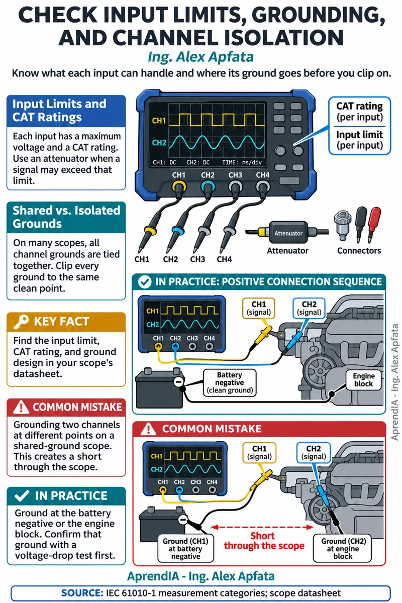
    3. Check Input Limits, Grounding, and Channel Isolation
    4. Back-Probe Without Damaging Terminals or Seals
    5. Set Voltage per Division, Probe Scaling, and Coupling
    6. Set Time per Division and Capture Detail
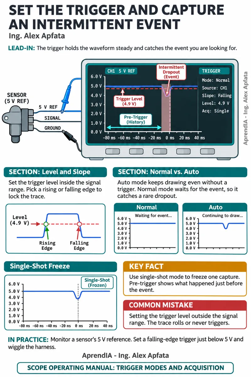
    7. Set the Trigger and Capture an Intermittent Event
  3. Unit 3: Test Crankshaft and Camshaft Signals

    1. Identify the Sensor Circuit Before You Connect
    2. Capture a Variable Reluctance Sensor Signal
    3. Capture a Hall-Effect Sensor Signal
    4. Read Reluctor Teeth, Gaps, and Repeating Features
    5. Compare Crank and Cam Timing on Two Channels
    6. Find Dropouts, Noise, and Unstable Signal Levels
    7. Follow a Crank-No-Start Signal Check
  4. Unit 4: Test Engine Control Sensors

    1. Check Sensor Power, Ground, and Reference Circuits
    2. Read a Conventional Narrowband Oxygen Sensor
    3. Identify What You Can Measure on an Air-Fuel Ratio Sensor
    4. Test a Mass Airflow Sensor with a Voltage Output
    5. Test a Mass Airflow Sensor with a Frequency Output
    6. Sweep a Throttle Position Sensor for Dropouts
    7. Compare Related Sensor Signals During a Symptom
  5. Unit 5: Read Ignition Primary and Secondary Patterns

    1. Choose Safe Ignition Probes and Test Points
    2. Read Coil Control and Dwell
    3. Read a Primary Voltage Pattern
    4. Read a Coil Current Ramp
    5. Find Firing, Burn, and Oscillation Features
    6. Compare Secondary Patterns with Coil-on-Plug Pickups
    7. Use Ignition Evidence to Plan a Misfire Test
  6. Unit 6: Test Fuel Injector Circuits

    1. Identify Injector Drivers and Safe Test Connections
    2. Read a Port Injector Voltage Pattern
    3. Read Injector Current and Opening Features
    4. Recognize Saturated and Peak-and-Hold Drive Patterns
    5. Recognize Direct Injection Test Limits
    6. Separate Electrical Evidence from Fuel Delivery
  7. Unit 7: Check CAN Bus Signals

    1. Find the Network and Confirm Your Test Point
    2. Capture High-Speed CAN High and CAN Low Together
    3. Read Dominant, Recessive, and Differential Signals
    4. Spot Distortion, Noise, and a Stuck Bus
    5. Check Termination Under the Correct Power Conditions
    6. Combine Scope Evidence with Network Fault Codes
  8. Unit 8: Build Your Diagnostic Routine

    1. Set Up a Starter Current Capture for Relative Compression
    2. Compare Compression Peaks and Confirm Your Findings
    3. Capture Charging System Ripple Under Defined Conditions
    4. Compare Known-Good Waveforms Under Matching Conditions
    5. Follow the Routine: Symptom, Test, Evidence, Next Step
    6. Verify the Repair and Build Your Waveform Library
  9. Glossary: Scope and Diagnostic Terms

Before you start

What does my purchase include?+

This digital PDF guide, United States edition, for personal use. No printed books, other titles or subscriptions.

Can I read it on my phone?+

Yes. Open the PDF on your phone, tablet or computer with any PDF reader.

How do I get the book and how can I pay?+

Checkout opens Stripe (card) or PayPal and you see the amount before confirming. As soon as the payment is verified you download the PDF and get an email with your private access link. The whole thing takes under 2 minutes.

What if it is not what I need?+

You have 30 days from purchase to ask for a refund by replying to your order email. We refund the full amount to the same payment method, no questions asked.

$27.00USD · digital PDF

YOUR NEXT READ

Make it yours.

Automotive Oscilloscope Diagnostics: The Visual Guide for Technicians

PDF · One-time payment$27.00 USD

Checking availability…

Have a coupon?

Stripe processes the payment. When you come back you can download your book, and we email you the link.

Book page